PCB Parametric Audio Equalizer

This project is based on the parametric equalizer proposed by Elektor in the late 80s or early 90s and later published in the book "Creations electroniques" in 1993 (Publisher: Publitronic). Their design involved three stereo potentiometers per channel, which means a lot of cables from the front panel to the circuit board. It's quite tiedous to build and IMHO prone to noise from within the enclosure. To solve these problems and make the unit more compact I have put everything on a single board, potentiometers included. No more cables!

A graphic equaliser has only one control per band: the gain. A parametric equaliser has 3 controls: gain, frequency and width. While a graphic equalizer requires a lot of bands to correct the sound, a parametric equaliser is more acurate and usually only one to three filters are used in series.

Several modifications were made to allow these improvements. First, it's an all-SMD board: easier and cheaper to build. This is necessary because clearance is limited with the front pannel. More importantly, it is important to realize that several PCBs will be stacked next to each other for the different filtering stages (usually 3, as Elektor says) and therefor we have no space to extend the PCB without spacing the potentiometers too. The only other option would be to use DIL circuits and several stacked PCBs: not very practical or cost effective.
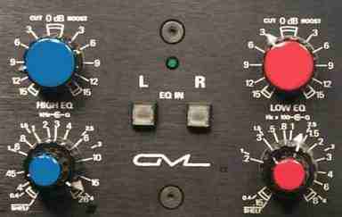
Brought to you from the man who invented the term “Parametric Equalization”, the 8200 has been an industry standard for over twenty years, and can be found on virtually every major recording studio’s stereo bus. Each of the five broadly-overlapping bands offers 15dB of Boost or Cut and adjustable bandwidth (or “Q”) from 0.4 to 4. The lowest and highest bands also can be switched to Shelf mode. Quite simply, the 8200 is the archetype Stereo Parametric Equalizer. Its extraordinary resolution, benchmark transparency, generous headroom, and surgical precision have been the reference for many other equalizers, but exceeded by no other. The 2U 8200 uses one 8355 PSU. .
The great advantage of a parametric equalizer is that it allows the user to change the frequency and Q. However, this is offset by the fact that this very ability complicates the inexperienced user's efficacious use the system. Adjustments can be so complex that the needed change might be difficult to determine.

A parametric equalizer uses knobs for its control functions, which makes it more difficult to visualize the set-up of the equalizer. Even so, it admirably performs the main functions of an equalizer which is to control the loss and gain in a frequency within a sound system.

Parametric equalizers usually have 3 to 6 bands. Some have overlapping frequency ranges. Others have broadband control which allows it to be used over the complete frequency range. Most parametric equalizers have a switchable range switch that allows operation in a x1 or x10 mode, allowing the frequency to be equalized on an even finer scale.

Found in almost every venue, the parametric equalizer certainly has its advocates, but it has by no means replaced the graphic equalizer as the preferred device for sound technicians.
A new type of second-order digital parametric equalizer is proposed whose frequency
response matches closely that of its analog counterpart throughout the Nyquist interval
and does not suffer from the prewarping effect of the bilinear transformation near the
Nyquist frequency. Closed-form design equations and direct-form and lattice realizations
are derived.

1. Introduction

Conventional bilinear-transformation-based methods of designing second-order digital parametric
equalizers [1–11] result in frequency responses that fall off faster than the corresponding analog
equalizers near the Nyquist frequency due to the prewarping nature of the bilinear transformation.
This effect becomes particularly noticeable when the peak frequencies and widths are relatively
high. Figure 1 illustrates this effect.
In this paper, we introduce an additional degree of freedom into the design, namely, the gain at
the Nyquist frequency, and derive a new class of digital parametric equalizers that closely match
their analog counterparts over the entire Nyquist interval and do not suffer from the prewarping
effect of the bilinear transformation.
The design specifications are the quantities {f , f , ?f, G , G , G, G }, namely, the sampling rate
s 0 0 1 B

f , the boost/cut peak frequency f , the bandwidth ?f , the reference gain G at DC, the gain G at
s 0 0 1

the Nyquist frequency fs /2, the boost/cut peak gain G at f0, and the bandwidth gain GB (that is, the
level at which the bandwidth ?f is measured.)
All previous methods of designing second-order equalizers assume G1 = G0 (usually set equal
to unity.) In these methods, the bilinear transformation is used to transform an analog equalizer
with equivalent specifications into the digital one. As remarked by Bristow-Johnson [9], all of these
designs are essentially equivalent to each other, up to a different definition of the bandwidth ?f and
bandwidth gain GB . For the equivalent analog equalizer, the quantity G0 = G1 represents the gain
at DC and at infinity, with the latter being mapped onto the Nyquist frequency f /2 by the bilinear
s

transformation.
In the method proposed here, we allow G to be different from G . In particular, we set G
1 0 1

equal to the gain an analog equalizer would have at f /2 if it were not bilinearly transformed. This
s

condition on G , together with the requirements that the gain at DC be G , that there be a peak
1 0

maximum (or minimum) at f0, that the peak gain be G, and that the bandwidth be ?f at level GB ,
provide five constraints that fix uniquely the five coefficients of the second-order digital filter.
The resulting digital filter matches the corresponding analog filter as much as possible, given
that there are only five parameters to adjust. The matching is exact at f = 0, f , f /2, and the two
0 s

filters have the same bandwidth ?f . These design goals are illustrated in Fig. 2.

†Presented at the 101st AES Convention, Los Angeles, November 1996, and published in JAES, vol.45, p.444, June 1997.

1

Tips how to cut Local Area Network LAN

1.using netcut software, dont even try to cut your server ip and yours, or you will be disconnected
2. winarpattacker, scan the connected network and choose the target
2.baned gateway
3. flooding
that's all maybe it is can help you

Electric Niccan leaf car

New electric Car from Nissan named Nissan leaf . powered by 100 electric source
Tecipe to create Classic deviled eggs recipe, perfect for post-Easter and summer picnic potlucks. Mashed cooked egg yolks, mixed with mayonnaise and Dijon, spooned or piped

Recent Post

eXTReMe Tracker
oes elektro diagram honda modif house luxury autocar zonadownload gossip celeb modif car