sukses montir TV/DVD/RADIO-TAPE/TV/Monitor/VCD/DVD
Monday, May 24, 2010 by sms
Needed to become a mechanic is not too expensive, namely:
Equipment
Good quality solder, preferably in the form of shots and saucer

Vacuum tin good quality, usually long
Tin solder good quality fishing brands such

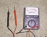
Multitester analog / digital
Some books are basic and digital electronics / repair
The main components such as resistors 1/4W to 10W, a high voltage capacitor, transistor amplifier for a standard monitor / TV, IC-IC amplifier, a standard transistor. If there are more funds, your collection of components of a total of approximately 1 jutat also ok, make the stock.
Patience and hobby. Instead you pay a mechanic take it to the handyman 75-300rb, mending your own try to fix first, Bener not?
Principles of Electronic Equipment Repair
Find out damage to the fuse / power supply, transistors, resistors, capacitors ic or by way of measuring it.
Replace the defective components.
Mentuning / or optimize the test results (eg turn trimpot, focus on the flyback etc.)
Measure Components
To measure the resistor value:
Attach two pieces to the second leg multitester pin resistor, whether or not soldered on the PCB which has been soldered on the PCB.
Look at the value indicated on multitester
If multitetester showed tremendous value once, most likely the resistor end. Resistors generally end on a high power resistor 2-15W. To ensure the accuracy of the value of resistors, resistor mounted on the PCB can you come off first.
If there are measurement deviations> 20%, it's like resistors are replaced with new ones.
Measuring Capacitors
To measure the capacitor, you simply do the following:
Connect the two pin + multitester to the anode capacitor, and pins - to the cathode capacitor
Change quickly multitester pin layout, if multitester show certain values and change gradually (down), means the capacitors are in good condition.
Measuring Diode
To measure the diode you simply connect the two pin diodes multitester by foot if shuffled back showing different values then the diode is in good condition, if the diode indicates the value is very large or very small likely break or short the diode should be replaced immediately.
Determination of the diode polarity: (a) Low resistance indicates a forward bias, the black lead and red lead is cathode anode (for most meters) (b) shows high resistance leads Reversing indicating reverse bias.


