How Catu Daya Linear works

Electronic devices should be powered by direct current supply DC (direct current) are stable to well. Battery or batteries are a source of DC power supply is best. But for applications that require larger power supply, the source of the batteries is not enough. A major source of power supply is the source of alternating AC (alternating current) from power plants. For that we need a power supply device that can convert AC into DC current. In this article presented the principles of the power supply circuit (power supply) linear ranging from the simplest rectifier circuit to the power supply was regulation.

Rectifier (rectifier)

Principle rectifier (rectifier) The simplest is shown in Figure-1 below. Transformer is needed to lower the AC voltage from the grid at the primary coil becomes smaller AC voltage on the secondary coil.


image 1: a simple rectifier circuit

In this circuit, diodes just continue to contribute to a positive voltage to the load RL. Which is called a half-wave rectifier (half wave). To obtain full-wave rectifier (full wave) is required transformer with center tap (CT) as in the picture-2.


image 2: full-wave rectifier circuit

Positive voltage phase of the first forwarded by D1, while the next phase which is passed through D2 to the load R1 with the transformer CT as a common ground .. Thus R1 burden gets a full wave voltage supply such as the picture above. For some applications such as for supply to small dc motors or dc incandescent lamp, the shape of this voltage is sufficient. Although the voltage ripple seen here from both series are still very large.


Image 3: half-wave rectifier circuit filter C Dengah

Figure 3 is a series of half-wave rectifier with filter capacitor C is parallel to the load R. Apparently with this filter discharge voltage waveform can be blended. Figure-4 shows the DC voltage output from circuit half-wave rectifier with capacitor filter. Bc line is approximately straight line with a certain slope, which in this state for the load current supplied by voltage capacitor R1. Bc line is not actually a straight line but exponential in accordance with the nature of the discharge capacitor.


image 4: filter capacitor waveform with

Bc curve slope depends on the large current I flowing to the load R. If the current I = 0 (no load) then the curve will form a horizontal line bc. But if the load the greater the flow, the slope of the curve will become sharper bc. The voltage that comes out will be shaped with a sawtooth ripple voltage of the magnitude is:

Vr = VM-VL ... ....... (1)

and dc voltage to the load is VDC = VM Vr / 2 ..... (2)
Good rectifier circuit is a circuit which has the smallest ripple voltage. VL is a voltage discharge or discharge the capacitor C, so it can be written:

VL = VM e -T/RC .......... (3)

If equation (3) disubsitusi to formula (1), it is obtained:

Vr = VM (1 - e -T/RC) ...... (4)

If T <

so if this disubsitusi to the formula (4) can be obtained by a simpler equation:

Vr = VM (T / RC) .... (6)

VM / R load is none other than I, so that with this visible relationship between the load current I and the value of capacitor C to the ripple voltage Vr. This calculation is effective to obtain the desired ripple tengangan value.

Vr = I T / C ... (7)

This formula is to say, if I load current was higher, the greater the voltage ripple. Conversely, if the capacitance C was higher, the voltage ripple will be smaller. For simplification is usually considered T = Tp, ie a period of one sine wave of the grid frequency of 50Hz or 60Hz. If the grid frequency of 50Hz, then T = Tp = 1 / f = 1 / 50 = 0.02 sec. This applies to half-wave rectifier. For full-wave rectifier, of course, the tuner frequency doubled, so that T = 1 / 2 Tp = 0.01 sec.

Full-wave rectifier with C filter can be created by adding a capacitor in the circuit of figure 2. Can also use a transformer without CT, but by assembling four diodes as shown below-5.


Image 5: full-wave rectifier circuit with filters C

For example, you designed the full-wave rectifier circuit of the power supply 220V/50Hz grid to supply the load of 0.5 A. What is the required capacitor value so that this circuit has a voltage ripple of no more than 0.75 Vpp. If formula (7) be inverted so obtained.

C = I.T / Vr = (0.5) (0.01) / 0.75 = 6600 UF.

For this size capacitor elco widely available type which has a maximum working voltage polarity and specific. Working voltage capacitors used must be greater than the power supply output voltage. Barangkalai now you understand why you create a series of audio hum, try to check the power supply rectifier circuit that you created, if the voltage ripple is quite disturbing. If not available in the market of such a large capacitor, can certainly memparalel two or three capacitors.

Regulator
The rectifier is good enough if its a small ripple voltage, but there are stability issues. If the voltage of electricity rise / fall, then the output voltage will also rise / fall. Like the rectifier circuit above, if the current higher voltage dc discharge was also decreased. For some applications this voltage changes quite annoying, so it requires an active component that can regulate the output voltage becomes stable.

The most simple regulator circuit shown in Figure 6. In these circuits, zener works on regional breakdown, resulting in an output voltage equal to or Fout Zener voltage = VZ. However, this circuit is only useful if the load current not exceeding 50mA.


6 pictures: Regulators Zener

The principle of such a power supply circuit is called a shunt regulator, one of his trademark is a regulatory component in parallel with the load. Another feature of the shunt regulator is susceptible to short-circuit. Notice when Fout connected short (short-circuit) then the current is fixed I = Vin/R1. In addition to a shunt regulator, there is also a series called by the regulator. The main principle of such series regulator circuit in Figure 7 below. In this circuit output voltage is:

Fout = VZ VBE ........... (8)

VBE is the base-emitter voltage of transistor Q1 of the magnitude of 0.2 - 0.7 volts depending on the type of transistor used. By ignoring the IB currents flowing at the base of the transistor, to determine the magnitude of R2 resistance that is needed is:

R2 = (Vin - VZ) / Iz .........( 9)

Iz is the minimum flow required by the zener diode to achieve the zener breakdown voltage. These large currents can be detected from a datasheet which amount to approximately 20 mA.


Image 7: regulator zener follower

If the supply current required is greater, of course the base of IB in the current calculation circuit above can not be ignored anymore. Where such a known, large currents will be proportional to IC flows dirumskan with IB or IC = BIB. For such purpose, the transistor Q1 is used can be replaced with Darlington tansistor which typically have large b values. With a Darlington transistor, the current small base that could produce a greater flow of IC.

Techniques that better regulation is to use the Op-Amp to drive the transistor Q, as in a series of eight images. Zener diodes are not here to give feedback directly to the transistor Q, but as a reference voltage for the op-amp IC1. Negative feedback on the op-amp pins are excerpts from the voltage regulator out, namely:

Vin (-) = (R2 / (R1 R2)) ....... Fout (10)

If the stress out Fout ascending, then the voltage Vin (-) will also be rising until the voltage is equal to the reference voltage VZ. And vice versa if the voltage decreases Fout out, for example because of supply current to the load increases, op-amp will keep the stability of the reference point by giving the current VZ IB to the transistor Q1. So that at any time maintaining the stability of op-amp:

Vin (-) = VZ ......... (11)


Figure 8: regulator with op-amp

By ignoring the VBE voltage of transistor Q1 and mensubsitusi formula (11) into formula (10) then obtained a mathematical relationship:

Fout = ((R1 R2) / R2) VZ ........... (12)

In this circuit the output voltage can be regulated by regulating a large R1 and R2.

Now it should no longer need to painstakingly search for the op-amps, transistors and other components to realize a series regulator as above. Because this kind of circuit has been packaged into a single fixed voltage regulator IC. Are now widely known as the 78XX series component of the voltage regulator remains positive and 79XX series which is a voltage regulator to remain negative. In fact, these components are usually already equipped with current limiting (current limiter) and also limiting the temperature (thermal shutdown). This component is only three pins and by adding some components alone can be a power supply circuit was good regulation.


Image 9: regulator with IC 78XX / 79XX

For example 7805 is a voltage regulator to get a 5 volt, 12 volt voltage regulator 7812 and beyond. While such 79XX series is the 7905 and 7912 which are respectively the negative voltage regulator 5 and 12 volts.

Apart from the fixed voltage regulators have a voltage regulator IC also can be arranged. The principle is the same as OP-amp regulator packaged in a single IC for regulators such as LM317 LM337 variable positive and negative variables for the regulator. The difference between resistors R1 and R2 are outside the IC, so that the output voltage can be adjusted via external resistors.

It's just important to know that with the IC regulator circuit can work, tengangan input must be greater than the output voltage regulatornya. Usually the difference in voltage Vin to Fout recommended in the datasheet component. Use heatshink (Aluminum cooling) is recommended if these components to be used to supply a large current. In the datasheet, these components can pass through the flow reaches a maximum of 1 A.

- End -
Needed to become a mechanic is not too expensive, namely:


Equipment
Good quality solder, preferably in the form of shots and saucer
Multitester analog
Vacuum tin good quality, usually long
Tin solder good quality fishing brands such
Multitester analog / digital
Some books are basic and digital electronics / repair
The main components such as resistors 1/4W to 10W, a high voltage capacitor, transistor amplifier for a standard monitor / TV, IC-IC amplifier, a standard transistor. If there are more funds, your collection of components of a total of approximately 1 jutat also ok, make the stock.
Patience and hobby. Instead you pay a mechanic take it to the handyman 75-300rb, mending your own try to fix first, Bener not?
Principles of Electronic Equipment Repair

Find out damage to the fuse / power supply, transistors, resistors, capacitors ic or by way of measuring it.
Replace the defective components.
Mentuning / or optimize the test results (eg turn trimpot, focus on the flyback etc.)
Measure Components

To measure the resistor value:

Attach two pieces to the second leg multitester pin resistor, whether or not soldered on the PCB which has been soldered on the PCB.
Look at the value indicated on multitester
If multitetester showed tremendous value once, most likely the resistor end. Resistors generally end on a high power resistor 2-15W. To ensure the accuracy of the value of resistors, resistor mounted on the PCB can you come off first.
If there are measurement deviations> 20%, it's like resistors are replaced with new ones.

Measuring Capacitors

To measure the capacitor, you simply do the following:

Connect the two pin + multitester to the anode capacitor, and pins - to the cathode capacitor
Change quickly multitester pin layout, if multitester show certain values and change gradually (down), means the capacitors are in good condition.
Measuring Diode

To measure the diode you simply connect the two pin diodes multitester by foot if shuffled back showing different values then the diode is in good condition, if the diode indicates the value is very large or very small likely break or short the diode should be replaced immediately.


Determination of the diode polarity: (a) Low resistance indicates a forward bias, the black lead and red lead is cathode anode (for most meters) (b) shows high resistance leads Reversing indicating reverse bias.
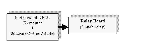
This kit is the application of parallel port as a controller device using relayboard. The following block diagram:Pin DB25 Centro SPP Signal Arah In/out Register Hardware di invert
1 1 nStrobe In/Out Control Ya2 2 Data 0 Out Data
3 3 Data 1 Out Data
4 4 Data 2 Out Data
5 5 Data 3 Out Data
6 6 Data 4 Out Data
7 7 Data 5 Out Data
8 8 Data 6 Out Data
9 9 Data 7 Out Data
10 10 nAck In Status
11 11 Busy In Status Ya
12 12 Paper-Out / Paper-End In Status
13 13 Select In Status
14 14 nAuto-Linefeed In/Out Control Ya
15 32 nError / nFault In Status
16 31 nInitialize In/Out Control
17 36 nSelect-Printer / nSelect-In In/Out Control Ya
18 – 25 19-30 Ground Gnd
If you want to control in Visual Basic. Net 2005, you can use as a provider inpout32.dll file functions to access I / O. Make sure if your Operating System using Windows 95 or older, use the program to grant permission Userport PC hardware access. Under this program can control the parallel port, or port ISA port addresses are set according to (378H or 300H), use the command:

Variabel_penampung = INP (& H "address") / / receive input

out (& H "address", sumber_data) / / removing data

Generally have a parallel port address 378H, while Port ISA begins from address 300H. If we want to control the parallel port using windows 1998 down, then there should be no additional programs, but if the Windows 2000 and above, use userport program that will give permission to access the port directly. You do this by copying the files userport.sys to the folder c: \ windows \ system32 \ drivers.

After that activate the program userport as follows:

Table Name the pins of parallel port DB 25 connector and the Centronics

High-Speed Data Acquisition and Generation

Click on the black blocks to appearance or sample recommended solutions

Design Considerations

High Acceleration Abstracts Accretion System
High-Speed Data Acquisition and Generation
A aerial acceleration abstracts accretion arrangement accouterments accelerated chip circuits to activate and access aerial abstracts amount breeze ascendancy and storing.

Core Subsystems include:

Analog Ascribe Front End - congenital about a accelerated ADC including accelerated Op-Amps, FIFOs, and SRAMs. The beck of abstracts achievement from the ADC is accounting into FIFOs, stored in blocks of SRAM, and beatific anon to the alfresco apple through registers beneath the ascendancy of the abstracts accretion argumentation in the FPGA.

FPGA - contains abstracts accretion controls and logics including the activate logic, absurdity detection, DSP interface, anamnesis abode decoder, counters, and achievement control. The ascendancy argumentation selects a abstracts accretion clock, processes altered triggers, and transfers the acquired abstracts to the centralized anamnesis of the abstracts accretion channels.

Analog Achievement - congenital about a accelerated DAC, including Op-Amp and achievement abstracts buffer.

High-Speed Bus Interface - transfers abstracts through accelerated alongside bus on the aback even (PCI,VMEbus) or accelerated Ethernet.

Clock Source - provides alarm for altered abstracts accretion options and modes.

Power Managements - converts the ascribe ability from the backplane to run assorted anatomic blocks.
Traditional NI-DAQ (Legacy) Support

Traditional NI-DAQ (Legacy) is included for FREE with every device that the Traditional NI-DAQ (Legacy) application programming interface (API...download the latest version of Traditional NI-DAQ (Legacy) for FREE, and now you can order copies...

LabVIEW for Wireless Sensor Networks Support

The NI LabVIEW Wireless Sensor Network (WSN) Module Pioneer extends the LabVIEW graphical programming environment to create and deploy embedded applications to programmable NI WSN measurement nodes. Use LabVIEW WSN Pioneer to extend battery life by optimizing node behavior, perform custom analysis,

NI USB-TC01 Support

The NI USB-TC01 thermocouple measurement device features NI InstantDAQ technology so you can instantly take temperature measurements with your PC. Just plug it in and built-in software for viewing and logging data automatically loads. No driver installation is necessary. Connect to any USB port to

NI PXIe-6356 Support

NI X Series multifunction data acquisition (DAQ) devices provide a new level of performance with the high-throughput PCI Express bus, NI-STC3 timing and synchronization technology...

NI WLS-9234 Support

The NI WLS-9234 is a four-channel IEEE 802.11 wireless or Ethernet C Series dynamic signal acquisition module for making high-accuracy audio frequency measurements from integrated electronic piezoelectric (IEPE) and non-IEPE sensors. The WLS-9234 delivers 102 dB of dynamic range and incorporates

NI PCIe-6361 Support

NI X Series multifunction data acquisition (DAQ) devices provide a new level of performance with the high-throughput PCI Express bus, NI-STC3 timing and synchronization technology...

NI PXIe-6366 Support

NI X Series multifunction data acquisition (DAQ) devices provide a new level of performance with the high-throughput PCI Express bus, NI-STC3 timing and synchronization technology...

NI PXIe-6368 Support

NI X Series multifunction data acquisition (DAQ) devices provide a new level of performance with the high-throughput PCI Express bus, NI-STC3 timing and synchronization technology...

NI PCIe-6353 Support

NI X Series multifunction data acquisition (DAQ) devices provide a new level of performance with the high-throughput PCI Express bus, NI-STC3 timing and synchronization technology...

NI PXIe-6341 Support

NI X Series multifunction data acquisition (DAQ) devices provide a new level of performance with the high-throughput PCI Express bus, NI-STC3 timing and synchronization technology...
Article Information:
Title: Optical tomography system using microprocessor and ethernet controller-based data acquisition system
Author(s): Ruzairi Abdul Rahim, Goh Chiew Loon, Mohd. Hafiz Fazalul Rahiman, Chan Kok San, Pang Jon Fea, Leong Lai Chan
Journal: Sensor Review
Year: 2010 Volume: 30 Issue: 2 Page: 124 - 129
ISSN: 0260-2288
DOI: 10.1108/02602281011022715
Publisher: Emerald Group Publishing Limited
Document Access:
Existing customers:
Please login above.
You do not have rights to view the article

Purchase this document:
Price payable: GBP £13.00
plus handling charge of GBP £1.50 and VAT where applicable.
Purchase

Request this document:
Print or e-mail a document request to your librarian.
Request

Reprints & permissions:
Request

Abstract: Purpose – Owing to the high cost of data acquisition (DAQ) card in the market, the purpose of this paper is to develop a high speed, low-cost microprocessor and ethernet controller-based DAQ in optical tomography system.

Design/methodology/approach – Microprocessor is the main core to control the sensor circuitry while ethernet controller has the responsibility of transmitting data to PC and thus insuring the reliability of data.

Findings – The data transfer rate will be up to megabytes per seconds. In this optical tomography system, projection geometry combining two orthogonal and two rectilinear in one layer is modeled.

Originality/value – This paper presents a new application in optical tomography.

Keywords: Controllers, Data collection, Image processing, Infra-red devices, Microcontrollers
Article Type: Research paper
Article URL: http://www.emeraldinsight.com/10.1108/02602281011022715
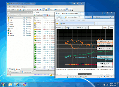
IntegraXor is an award-winning HMI/SCADA software with clear animation, absolute time accessory connectivity, anxiety functions, database logging, trending and advertisement as basal functions. It is a complete apparatus for architecture adult and able real-time automation systems.
Pioneering Web SCADA

It is advised from arena up application web technologies and offers fast, simple and aboveboard development application HTML and Javascript which are broadly accepted IT skills. It uses a web-browser as the front-end and SVG web cartoon for decision and animation.

Since the aboriginal accession in 2003, IntegraXor has appear a continued way in alms a HMI/SCADA software that is solid reliable, dependable and scalable.

IntegraXor accept been auspiciously implemented in assorted locations about the world. Many of IntegraXor applications are analytical acute 24x7 operation.

Among the companies that we accept provided solutions and casework to are

Petronas - Oil & Gas

BiL - Oil & Gas

FMC Technologies - Oil & Gas

Perodua - Automotive

Allegiance - Healthcare

Bredero Shaw - Oil & Gas

Yokogawa - Oil & Gas

Standard Animation

The appellation "Animation" in SCADA/HMI refers to change of blush or size, movement that reflect the real-time accompaniment of a tag which is commonly associated to a device's status. Basal action consists of Color, Level/Bar, Text, Rotation, Position, etc. Below is an activated clear that simulates some actual basal apparatus of SCADA animation.

Recent Post

eXTReMe Tracker
oes elektro diagram honda modif house luxury autocar zonadownload gossip celeb modif car